Welcome to our Stormworks Build and Rescue KAP-140 Autopilot Guide. A guide on how to operate and use my autopilot and flight planner: The KAP or SW 140.
Stormworks Build and Rescue KAP-140 Autopilot Guide
A guide on how to operate and use my autopilot and flight planner: The KAP or SW 140.
General Layout of the Autopilot and Flight management screens
The Auto PilotThe KAP-140 I have created is loosely based off the KAP-140 Autopilot in real life. The Auto Pilot is split into two distinct areas:
1) The Autopilot Mode Panel

This displayed the armed or engaged modes of the Autopilot.
To the right it displays the target Altitude (If the Alt mode is engaged) with the selected units of either feet or meters. For the displayed Auto pilot mode annunciation meaning go to the Autopilot mode and indications chapter.
2) The Selection Panel

This is how you select your autopilot modes and engage the autopilot. On the left in its own area is the autopilot engage button. In the middle is the heading modes including arrival engagement and on the far right is the Altitude mode section. The circle represents the dial you would turn and is used to select a target altitude.
The Flight Management System
The flight management system is a basic way to plan routes and fly them somewhat accurately and integrates directly into the KAP-140. It consists of 4 pages.
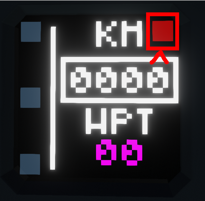
1) The Main Screen

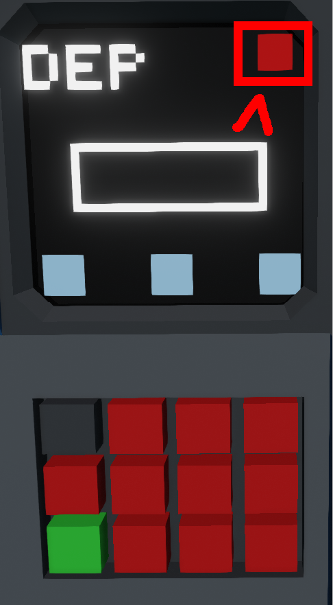
On the left from top to bottom we have the selection for the Departure, Enroute and Arrival Pages. The Red button in the top right corner deletes the entire flight plan.
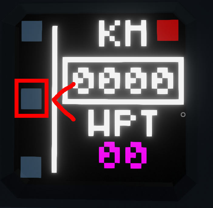
In the main section we have a distance read out of the entire route and lastly how many waypoints the flight plan includes. These currently do not update as the distance or number of waypoint decreases.
In theory this can be an infinite amount but the text is only so far configured for 99 way points.
2) The Departure screen

The departure screen is a mirror of the arrival screen and consists of 3 main buttons on the bottom. From right to left this is: Commit the value from the keypad as the X co-ordinate, Commit the value from the keypad as the Y co-ordinate and lastly Commit the value from the keypad as the target track.
This will be more clearly discussed in How to Program the Flight Management System Chapter. The central white button is the commit to the system button: This takes all the stored values and commits them to the flight plan. The Top right is the BACK button to take you back to the Main Screen.
3)The Enroute Screen

The enroute screen shares similarities between the departure and arrival screens, the X and Y buttons are the same and the commit button is the same. However, you cannot input a target track. The micro controller automatically calculates the target track from the last waypoint to your desired point once the commit button is pressed.
4) The Arrival Screen

This is a direct copy of the departure screen and shares exactly the same functionality.
Auto Pilot modes and indications
In this chapter we will look at all the available Autopilot annunciations and what they mean for you as the pilot.
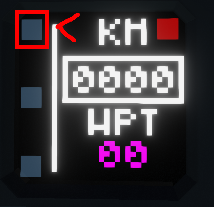
Boxed A
This is by far one of the most important annunciations to be displayed, without it the entire system will not work. This A shows that the autopilot is engaged in the desired modes. In this image, no modes are selected so the autopilot will do nothing, however you will still retain control of the aircraft.
HDG and NAV Buttons The next annunciations are to do with the lateral tracking of your aircraft. 
Hitting the H button of the central panel will put you into heading mode: This targets the heading you are on as you select the mode. This can be preloaded without the autopilot on before take off if so desired.
Hitting the N button will load the NAV mode, this is following the target track as inputted from the Flight Management Screen. It is highly recommend that for take off, you have NAV and the Autopilot Selected on for best use.
Alt and Baro ButtonsThe next buttons are on the far right by the circle. These are the Alt and Baro modes.
Firstly the target altitude can be selected using the disk to the right. Touching to the right of it will raise the target altitude, to the left will lower.
Hitting the A button on the right of the panel engages the Alt mode. This will now target the altitude that is selected. It must be noted it will do this regardless of speed, so if you are throttle idle and selecting a higher altitude, it will pitch to try and reach it and you will enter a stall. It remains the pilots responsibility with this autopilot to manage the speed.

Hitting the B button changes the units from FEET or FT as displayed to Meters or M as displayed, this gives an easy switch if you do not operate using FT as your altitude measurement.
The AR ButtonThe AR button is the ARRIVAL button. Selecting this mode will engage NAV mode and put you into the LDG Vertical guidance if appropriate. This is determined by how far off the calculated glide path you are. You can select this using the property on the chip, in this case its 3 degrees. If you are below 2.5 degrees the LDG mode is armed like so:
This will ensure you will keep your target Alt until on a suitable path for the glide down. Once you have passed this threshold, the LDG mode will become engaged like so:
This is designed so that you don’t get weird climbs to chase the glide path, but to intercept it.
Programming the Flight Management System – Stormworks Build and Rescue KAP-140 Autopilot
In this chapter, we will look at how to program the flight management system. We will do this for a 5 waypoint route with a departure, enroute and then finally an arrival.
Note: Due to me being slightly lazy, its important you follow the programming from Departure, Enroute then Arrival to ensure nothing out of the ordinary happens.
For help there are a few headings for airfields that we need to know that aren’t obviously north south (0 or 180 running) this excludes the desert but goes as follows:
| Name | Headings |
| Dreimor | 040 or 220 |
| Harrison Airbase | 040 or 220 |
| ONiell Airbase | 130 or 310 |
| Military Island | 030,210,110 or 290 |
| Arctic Airfield | 140 or 320 |
| Multiplayer Base | 040 or 220 |
Alright now to the programming of the Flight management system:
Departure
From the main page use the top left button to select the departure page.
This will take you to the following page:
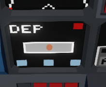
DEP at the top marks that this is the departure page. We now need to work out what our co-ordinates will be for our departure.
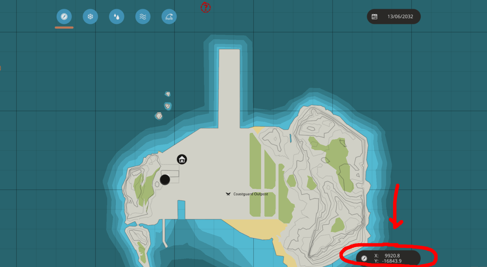
Using the in game Map, gather your starting departure co-ordinate. Do this by hovering your mouse over the point you will line up on the runway and take off from and making a note of the co-ordinates in the bottom right of the screen.
Note: If you are not aware, different seeds will have different co-ordinates so the ones displayed will not work on a different map.
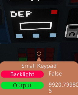
With this information, now go to the keypad below the Screen and key in the X co-ordinate like so
Note: The Keypad can sometimes display a weird value, if its within 0.1 its pretty much okay like the following
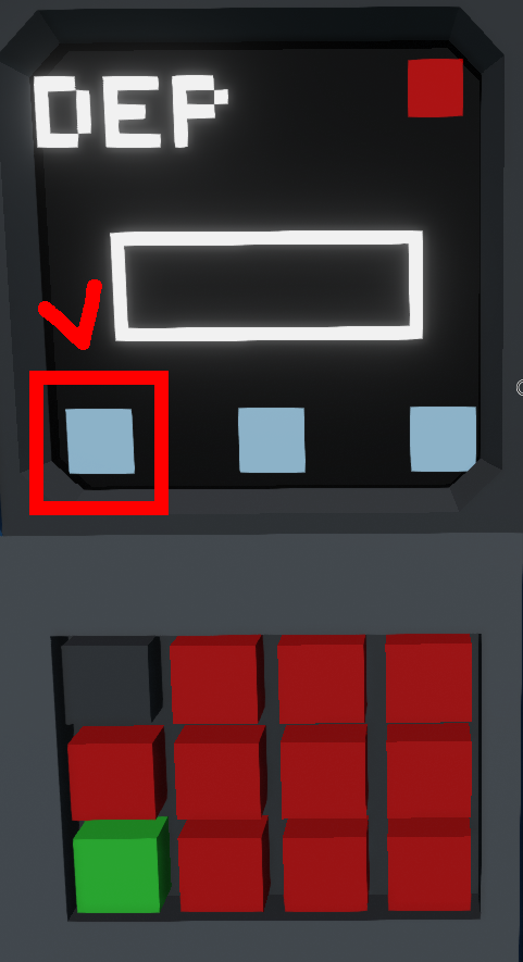
To assign this to the X you now click the bottom left button.
To add the Y co-ordinate you input the number in the keypad but instead of hitting the left button, you now hit the middle button on the bottom as shown here:

Lastly we will want to input a heading, in this case the heading I will target is 0 or north. As the X and Y I input this into the keypad then hit the bottom right button. This has now assigned values for the X, Y and Heading for the flight plan, but it is not commited. To do this you hit the central button pictured here:
This will then add the waypoint which is reflected on the map display and total waypoints like so:
By default on this chip, the departure track is set to 5km, this means your plane will fly out 5kms before turning to the next waypoint. For arrival it is set at 12km.
Note: While you can change the departure distance, it is recommend that you leave the arrival distance for now, as this helps aid with the arrival function.
You will note that the waypoints has gone to two. This is because the system has generated a point on the target track out at 5km away so 2 waypoints exist in the flight plan.
Enroute – Stormworks Build and Rescue KAP-140 Autopilot
The process for enroute is exactly the same but with the lack of ability to select a target heading. To go back to the main page hit the red button on the DEP screen in the Top Right.
Do this only once as the one in the Main page will delete the flight plan and you will have to start again.
To add an enroute section go to the second button down on the main page.
Clicking this brings you to this page:
The layout is much the same as the departure and arrival screen but as stated above, you cannot add a target track, this is calculated from your last waypoint automatically.
The X and Y button work exactly the same, input your desired X and Y exactly as you did with the Departure X and Y. This can be done by finding the point you want on the map and making a note of the co-ordinates. The Commit and back buttons work exactly the same.
Note: It is recommend to make gentle waypoints for large turns beyond 90 degrees, while you can skip this, the autopilot will get a heap of a turn on rather rapidly.
Arrival – Stormworks Build and Rescue KAP-140 Autopilot
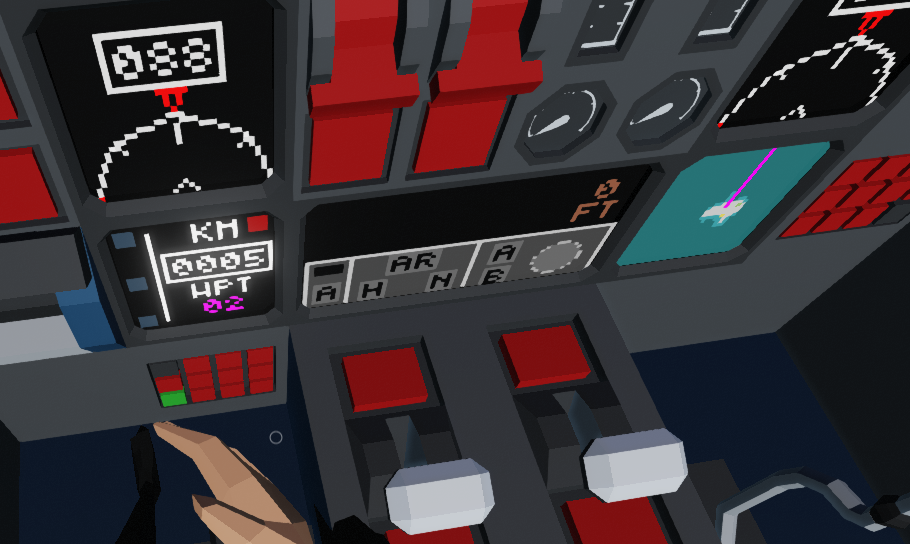
Lastly the Arrival segment. Going back to the main page, select the bottom button on the right side. This will take you to the Arrival Screen as indicated by ARR at the top.
The process is exactly the same as for the Departure. Select the X and Y on the touchdown zone or threshold of the runway you are going to land on. This best helps with the vertical guidance in Arrival mode for the Autopilot. You will note that once this is committed, the Map display will have this last track in Magenta rather than green, this is to indicate its the last track in the flight plan and, more importantly, what the glide path is being calculated along.
Deleting the Flight plan
Once the flight is completed or you want a new route entering, select the top right red button on the main page
This will delete the flight plan and reset the waypoints to 0. You will now be able to reprogram the flight plan and continue.
On next iterations, I will make this so you can select waypoints to delete, for now its rather rudimentary
Connecting the logic
Well well you’ve finished building your plane? What a beaut!
I must say that this is the fun part of this autopilot and Flight management, it has been tested on one aircraft so you folks wiring this thing up and flying with it will be interesting.
Please feedback your findings and if anything doesn’t work then we will work it out together
Alright lets begin with
Wiring the AutopilotFor this wonderful task you will need the following:
- A 1×2 display
- An Altimeter
- A Compass (Arrow pointing to the FRONT of the aircraft)
- A Linear speed sensor(Any Direction)
- Some Switch boxes for Rudder, Aileron and Elevator
When I get round to it the switch boxes eventually won’t be required, this is my first pass on the system so in time it will be refined.
Using the logic nodes connect the sensors to the labelled inputs/outputs.
Touch screen goes to the Autopilot screen.
FMS composite input goes to the Output of the FMGC Mk1 chip made by myself.
Ensure everything is powered (Namely screen and compass sensor) and the display has a constant on signal or way to toggle on and off.
For the switch boxes, the ON value should come from the autopilot, the off value should be your control inputs. The switch for rudder and aileron is the AP+HDG output and for the Elevator is the AP+Alt output.
The Autopilot should now work but without the FMGC Mk1 chip, the Nav and Arrival modes should be considered inoperative.
Wiring the FMGC Mk1 Chip

So you finished wiring your Autopilot up, now time for the next chip.
For this wiring adventure you need the following:
- 2 1×1 displays
- A GPS
- A Keypad
While Compass is listed, it is not required for this version of the FMGC.
Wire these up appropriately into the aircraft, again with the displays ensure they are powered, along with the GPS and make sure the displays have an on off value so the screen actually comes on.
For Composite input, ensure this is connected to the screen that will house the flight plan and not the map, otherwise the touch screen will not work.
Lastly the composite output for AP goes into the KAP-140 chip.
This should now be fully integrated together and should work.
Known bugs
While I am somewhat proud of this autopilot it does have some flaws that I will be working on over time. This is due to some PID tuning and some questionable logic at best but is summarised here:
Alt Mode Dive and climb: It is recommend you engage Alt mode while level as if you are pitched too high, the aircraft will snap down before going back up. Low level this is not ideal and is due to the PID value which will be refined.
Nav mode: Target track too far: Again this is another PID logic thing, If you stray way too far off track and engage nav mode, it is going to end in an endless loop. The logic behind this at the moment is to target a closure rate to your track, which should not exceed 80% of your current speed in meters per second. However this doesn’t work and needs refining. If you are going to operate in Nav Mode it is recommend you stay in it up until autopilot disconnection
Arrival mode glide path: This autopilot targets a glide path and it just needs some refinement, the path is a little too steep at the moment but will change with time when I refine it.
It must be noted that this autopilot is NOT Autoland capable. If you leave it in Arrival mode it will slap itself into the point you have chosen and then climb away as it tries to target the 3degree glide. Recommendation is down to a pretty standard ILS minima which is 200ft above the aerodrome elevation. For this reason disconnecting at 250-300ft is optimal so you can then guide it down to the runway.
Arrival mode tracking:
The tracking is good to within around 10 meters or so. While this is a low value, its not exact and can have you slightly displaced from the runway. This is being refined once I have the energy to revisit this section. It remains the pilots responsibility to ensure the correct lateral guidance is followed.
If any bugs are found I will add them here over time and try to address them when I am revisiting this little project.